Circuit Board Bottom-Side Assembly Instructions
Components, Equipment, Supplies Required
Components Required
37 PCS, 510 Ohm, Surface Mount Resistors 1206 Package
1 PC, Shockley Diode - SS34 Surface Mount (D0-214) Package
Equipment Required
Safety Glasses
Soldering Iron / Soldering Iron Stand / Wet Sponge
Rosin or No-clean Flux Core Solder
Tweezers
Resistor Basics
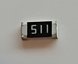
510 Ω Resistor, 1206 Package
Type and Value
-
510 Ω resistor: This means the resistor has a resistance of 510 ohms, which limits the current flowing through your LEDs to protect them from burning out.
-
The value is chosen because it balances brightness and safety — enough current for the LED to glow, but not so much that it overheats.
Package Style
-
1206 package: This refers to the resistor’s physical size in the Surface-Mount Device (SMD) format.
-
“1206” means the resistor is approximately 0.12 inches long × 0.06 inches wide (3.2 mm × 1.6 mm).
-
These are designed to be soldered directly onto circuit board pads, rather than having long leads like traditional through-hole resistors.
How to Read the Value
-
SMD resistors don’t use color bands like through-hole resistors. Instead, they often have numeric codes printed on top.
-
For a 510 Ω resistor, the marking is usually “511”:
-
The first two digits (51) are the base value.
-
The last digit (1) is the multiplier (×10).
-
51 × 10 = 510 ohms.
-
-
Some resistors may not have markings if they’re very small, so you rely on the packaging label or a multimeter to confirm the value.
Quick Summary
-
510 Ω = the resistance value.
-
1206 = the size of the resistor (SMD package).
-
Code “511” = how the value is marked on the resistor.
-
Purpose = limits current to protect LEDs.
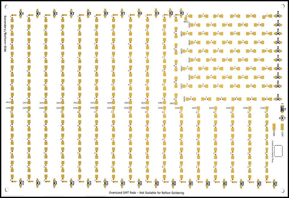
Bottom-Side Unpopulated Circuit Board-
Showing Surface Mount Component Locations
(See Illustration Below)
The component locations for resistors R1–R37, Shockley diode D1, and fuse F1 are printed on the bottom side of the circuit board.
SMT Resistors Installation Procedure
Step # 1
Locate Surface Mount Resistor Soldering Pads
(See Illustration # 1)
Step 1: Locate the Surface-Mount Resistor Pads
On the bottom side of the PCB, locate the soldering pads designated for surface‑mount resistors. These pads are labeled R1 through R37, with R1 and R2 shown below as examples.
Example: R1 & R2 Resistor Soldering Pads
(Step # 1 Illustration)

Step # 2
Prepping the Solder Pad
(See Illustration # 2)
Step 2: Prepping the Soldering Pad for Surface-Mount Resistor Installation
How to Tin a Surface-Mount Resistor Pad
1. Clean and Tin Your Soldering Iron Tip Make sure your soldering iron tip is clean and well-tinned. A clean, shiny tip transfers heat much better.
2. Position the Soldering Iron Place the tip of the iron firmly on the solder pad. Apply gentle pressure to ensure good thermal contact. Hold it there for 1–2 seconds to heat the pad.
3. Apply Solder While keeping the iron on the pad, touch the solder wire to the point where the iron tip meets the pad (not directly to the iron). The solder should melt and flow smoothly onto the pad within few seconds.
3. Create a Small Solder Bump You want a small, smooth, shiny dome of solder that completely covers the pad. Remove the solder wire first, then lift the iron away cleanly, and allow the solder to cool.
Tip: A properly tinned pad should look smooth and shiny.
(Step # 2 Illustration)

Tin pad with solder, to create a solder bump.
Step # 3
Initial Placement - Tack Soldering the Resistor to the Pad
(See Illustration # 3)
Step 3: Tack Soldering the Resistor to Its Pad
Using a clean, tinned soldering iron tip.
-
Using a pair of tweezers, grasp the surface-mount resistor by the sides of its body.
-
Align the resistor so it is centered between the two soldering pads and lies flat against the circuit board.
-
While holding the resistor in place, heat the soldering pad that was previously tinned.
-
As the solder melts (reflows), it will bond to the metal contact on the end of the resistor.
-
Once the solder becomes molten and attaches to the resistor’s contact, remove the soldering iron.
-
Continue holding the resistor in place with the tweezers until the solder cools and solidifies — about 3 seconds.
-
After cooling, release the resistor. One end should now be tack-soldered to the pad.
This entire process should take only a few seconds: approximately 2-3 seconds to reflow the solder and 3 more seconds for it to cool and set.
(Step # 3 Illustration)

Use tweezers to place the resistor flat on the PCB, centered between the two pads. Reflow the solder to tack it in place.
Step # 4
Soldering the Opposite Side of the Tack Soldered Resistor
(See Illustration # 4)
Step 4: Soldering the Opposite Side of the Resistor
Using a clean, tinned soldering iron, heat both the unsoldered side of the resistor contact and its pad simultaneously. Feed solder directly into the point where the soldering iron tip, pad, and resistor contact meet.
The solder should flow smoothly, covering the entire pad, bonding the resistor contact to the pad. Once the solder has flowed evenly, remove the soldering iron and allow the joint to cool for at least 3 seconds so the solder can solidify.
If rework is needed, clean the soldering iron tip before trying again. Any excess or burned solder residue on the tip can prevent proper heat transfer and result in a poor-quality solder joint.
(Step # 4 Illustration)
Solder the opposite side of the resistor to its soldering pad.

Step # 5
Reflowing the Solder Joint of the Tacked-Side of the Resistor - Completing the Resistor Soldering Process
(See Illustration # 5)
Step 5: Reflowing and Final Inspection
Using a clean, soldering iron tip, reflow the resistor’s tacked side solder joint by positioning the iron so that it makes contact with both the resistor’s metal contact and its solder pad. Apply a small additional amount of solder to the joint as needed to obtain proper wetting. Once the solder flows and covers the pad evenly, and the resistor metal contact remove the soldering iron tip and allow the joint to cool.
Visually inspect both solder joints and rework, if necessary, always starting with a clean soldering iron tip.
Important: If you rework one side of the resistor’s solder connection, allow at least 4–5 seconds before reworking the opposite side. Attempting to reflow both sides before the first joint has cooled and solidified may cause the resistor to shift out of alignment or become dislodged from the pads.
(Step # 5 Illustration)

Reflow the solder joint on the tacked side of the resistor, adding a small amount of solder ensuring good wetting to create a reliable electro-mechanical connection.
Shockley Diode D1 Installation Procedure
Shockley Diode - SS34
Surface Mount (D0-214) Package

Cathode (-): Identified by the line or band marking on the diode body.

Step # 1
Identify the Shockley Diode Soldering Pads
(See Illustration # 1)
Shockley Diode Soldering Pads Illustration
(Step # 1 Illustration)
(-) Negative polarity sign, showing the correct orientation of the diode.
Two soldering pads labeled D1- show the location of diode-SS34

Step # 2
Tinning the Diode Pads – Pre‑Installation
(See Illustration # 2)
Step 2: Prepping the Soldering Pad for Surface-Mount Diode Installation
How to Tin a Surface-Mount Diode Pad
1. Clean and Tin Your Soldering Iron Tip Make sure your soldering iron tip is clean and well-tinned. A clean, shiny tip transfers heat much better.
2. Position the Soldering Iron Place the tip of the iron firmly on the solder pad. Apply gentle pressure to ensure good thermal contact. Hold it there for a few seconds to heat the pad.
3. Apply Solder While keeping the iron on the pad, touch the solder wire to the point where the iron tip meets the pad (not directly to the iron). The solder should melt and flow smoothly onto the pad within 2–3 seconds.
3. Create a Small Solder Bump You want a small, smooth, shiny dome of solder that completely covers the pad. Remove the solder wire first, then lift the iron away cleanly, and allow the solder to cool.
Tip: A properly tinned pad should look smooth and shiny.
(Step # 2 Illustration)

Tin one of the diodes soldering pads to create a small solder bump.
Step # 3
Tack Soldering the Diode into Place
(See Illustration # 3)
Tack Soldering the Diode into Place
Using tweezers to hold the diode, align the diode between its two pads.
While continuing to hold diode D1 in position—aligned between its two solder pads and flat against the circuit board—with one hand, use your other hand to hold the soldering iron.
Heat the diode’s metal termination and the pad until the solder becomes molten. Then, carefully remove the soldering iron while maintaining the diode’s position until the solder cools and solidifies, securing that side of the diode in place.
Allow enough time for the solder to fully cool and solidify prior to releasing the body of the diode, with your tweezers. About 3-5 seconds, at which time you can release the body with your tweezers.
(Step # 3 Illustration)
Tack Soldered
D1

Using tweezers, hold diode D1 by the sides of the package (avoiding the terminations) and position the diode in the center of the two pads, and reflow the solder bump to tack solder the diode into place.
Step # 4
Soldering the Opposite Side of the Diode
Soldering the Opposite Side of the Tacked Diode
Using a clean, tinned soldering iron, heat both the unsoldered side of the diodes contact and its pad simultaneously. Feed solder directly into the point where the soldering iron tip, pad, and diodes contact meet.
The solder should flow smoothly, covering the entire pad and bonding the diode contact to the pad. Once the solder has flowed evenly, remove the soldering iron and allow the joint to cool for at least 3 seconds so the solder can solidify.
(Step # 4 Illustration)
Solder the Opposite Side of the Tacked Diode

D1
Step # 5
Reflow the Tacked Side of the Diode and Add a Small Amount of Solder
Reflow the tacked side of the diode by reheating the joint with your iron, then add a very small amount of flux‑core solder wire.
(Step # 5 Illustration)
D1
Reflow the Tacked Side of Diode Adding a Small Amount of Flux-Core Solder.
Fuse F1 Installation Procedure
SMT 1206 Fuse, 1-amp

Assembly Instructions: Fuses are non‑polar components. Install the SMT 1206, 1‑amp fuse using the same procedure as the resistors: tin one pad, tack‑solder the fuse, solder the opposite pad, then reflow the first joint with a small amount of fresh solder.
F1 Fuse Location

Highly Recommended Resistance Testing Validation
Prior to moving on to the top‑side circuit board population, it is recommended that you perform resistance tests to verify that all 37 resistors are properly soldered to their pads.
Using a multimeter, place one lead on the negative side of the D1 solder pad and the other lead on the LED pad closest to the 510‑ohm resistor. Verify that the measurement is approximately 510 Ω (within the expected tolerance). Repeat this procedure for each of the 37 resistors to ensure they are all properly soldered to their pads and making solid electrical contact.
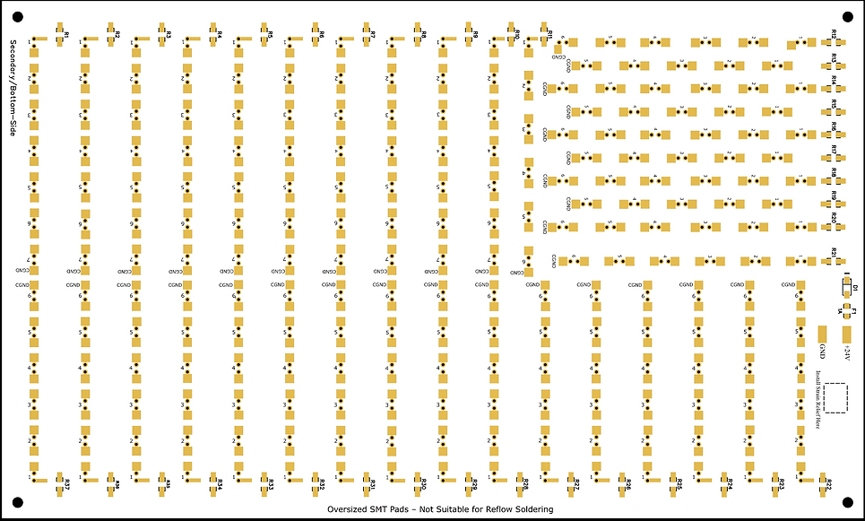
PCB Bottom-Side Fully Assembled